Heater Battery
Heater Battery
Application
Air-conditioner {AHU-FCU}, High Temperature Natteries, Load Bank of Generators, Industrial Drying Ovens , Heat Treatment, Offices, Buildings, Institutes, Retails , and Much More.
Available Types
Characteristics
Features
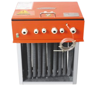
Construction:
Incoloy 800, Stainless Steel -321 Sheathing of tubular elements with/without finns. U/M shape elements are mounted on a detachable terminal plate using galvanized retainers. A mounting flange permits attachment to the duct work. Individual elements are easily replaced or interchanged. Where the application calls for a higher temperature, the case is constructed from heat resisting steels. A thermal Cut-out fitted for protection against overheating. Safety Auto Thermostat Cut-off required temp. Control, contractor and fan interlock device, SSR, SCR, BMS Compatible are available as optional extras, M / Explosion resistant covers (Flame Proof) and element are also available. Zero Clearance Construction / selected elements by calculated wire temperature method.
OPEN COIL CONSTRUCTION: Heating Elemetn Shall be Open coil 80% nickel 20% chrome type resistance wire shall be machine crimped into stainless steel. Terminals are supported by ceramic bushings staked into supporting brackets.
DUCT HEATERS FOR EXPLOSION / HAZARDOUS AREAS: - Daspass offer a wide selection of custom built electric duct heaters designs for outdoor, wet, dusty typical applications include use with roof top air-handling unit, in wash down areas such as food processing plants, wet & humid spaces neat indoor swimming pools, Sub-marine or Casino boat applications including shipboard use.
Calculating KW Requirement
Once the volume of airflow (CFM - in cubic feet per minute and the required temperature rise (Delta T degrees F ) through the heater are known , the required Kw rating ?(Kw) of the heaters can be determined from the formula :-)
KW (Capacity)= CFM x △ T0F / 3193
KW (Capacity)= Litter x △ T0C / 837
where the desired heating capacity in BTU / Hr is known the Kw is determined from the formula:-
KW (Capacity)= BTU / Hr / 3412
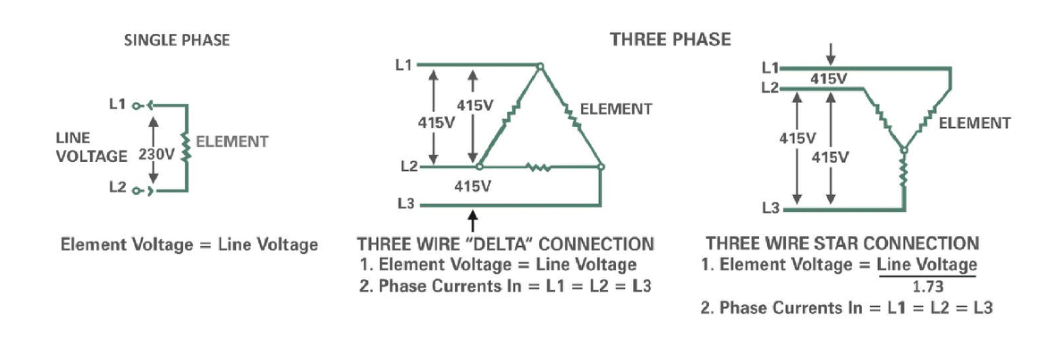
SINGLE PHASE ( 1 PHASE)
AMPERES = Watts / Line Voltage
THREE PHASE ( 3 PHASE)
AMPERES = Watts / Line Voltage x 1.73
The following load calculationand recommended operating ranges are based on standard 750 F entering air {comforting heating} Consult factory for the applications.
Heating Element Wiring Configurations
Installation Cautions :
Installation , Operating and Maintenance Manual Electrical Duct Heaters
FLANGE-IN-TYPE (FM) DUCT HEATERS
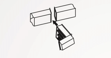
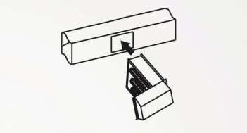
SLIP-IN-TYPE (SM) DUCT HEATERS
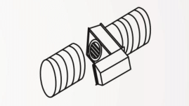
ROUND MOUNT (RM) TYPE DUCT HEATER
Rounf Mount Duct Heater are available for installation on round duct system with a 30 mm Extension on each side of the frame bny male and female adaptor
Read And Save These Installation Instruction
Caution , Risk of malfunction: In case alteration ( drilling holes or other ) to the electrical compartment , ensure proper protection of all electrical components installed . Chips may cause short circuit or effect operatin of electrical components .
General This document is to be used for all Duct ? AHU /FCU heaters installation unless the heater is used in apiece of equipment supersedes this documnent . In the case, it is the responsibility of the end user equipment manufacturer to have performed testing for the end use application
Application Information
Follow the procedure given on the sheet to find the minimum air velocity for safe operation. At least this minimum velocity must be provided at all points over the heater face area. Failure to meet this requirement may result in serious damage or nuisance thermal cutout tripping.
In the duct which may result in no uniform airflow. Duct elbows/ turns / fan of filters must be located at least 4 feet from the inlet of the heater and 2 free from the outlet of the heaters.
Mechanical Installation
Flange Type Heaters
Slip-In Type Heaters
Electrical Installation
Single Phase Line Current = Kw x 1000/ Voltage
Three Phase Line Current = Kw x 1000 / Voltage x 1.73
Donate us to achive our goal
Beguiled and demoralized by the charms of pleasure of the moment, so by desire,
that they cannot foresee.
that they cannot foresee.